ADONIS BPMN Guide
Welcome to the ADONIS BPMN Guide!
The Business Process Model and Notation (BPMN) is the leading standard for business process modelling developed by The Object Management Group (OMG) and supported by a wide range of vendors and employed by numerous organisations. Process modelling and documentation in ADONIS is fully based on the BPMN standard.
About This Guide
In the following documentation, you will find instructions on the Business Process Model and Notation, its latest rendering - BPMN 2.0, and how ADONIS incorporates this standard and expands it to fulfil modern business needs.
On This Page
- This section covers the definition and purpose of BPMN 2.0.
- This section covers the most important elements for modelling business processes.
- This section covers the BOC Group's extension of the BPMN 2.0 metamodel which enables modern BPM.
Modelling with BPMN elements in ADONIS
- This section ties together the aspects of the BPMN 2.0 standard with the modelling rules in ADONIS.
- This section covers different types of core process elements.
Learn More
Business Process Model and Notation specification
BPM Getting Started with ADONIS
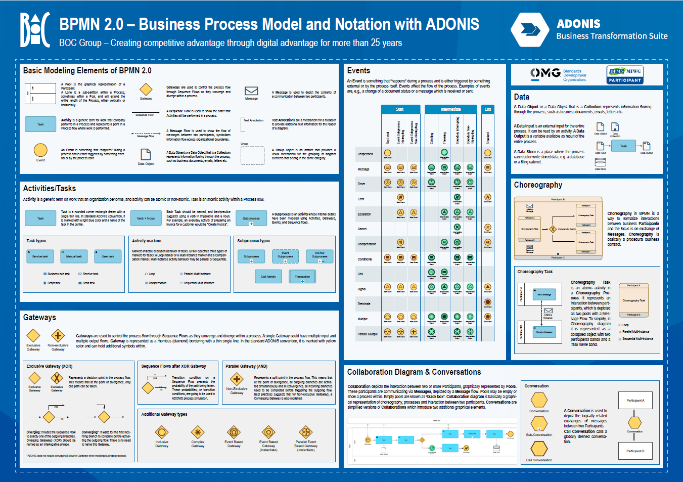
BPMN Overview
Business Process Model and Notation (BPMN) is a standardised graphical notation used for modelling and representing business processes in a clear and concise manner. It provides a visual representation of business workflows, allowing organsations to understand, document, and communicate their internal processes effectively.
The origin of Business Process Model and Notation (BPMN) dates back to the early 2000s when the need for a standardised graphical notation to model and communicate business processes became increasingly apparent. Before BPMN's development, various organsations and industries used their own proprietary notations, leading to inconsistencies, difficulties in understanding, and barriers for collaboration.
To address these challenges, the Business Process Management Initiative (BPMI) was founded in 2000. BPMI aimed to promote the standardisation of BPM and process modelling notations, leading to the creation of BPMN. The initial version of BPMN, known as BPMN 1.0, was released by BPMI in May 2004. It provided a foundation for a common visual language to describe business processes, facilitating cross-functional understanding and communication. At its conception, BPMN stood for Business Process Modelling Notation.
BPMN 1.0 was well-received, but it became apparent that improvements were necessary to address its limitations and make the notation more comprehensive and adaptable. As a result, the development of BPMN 2.0 began in 2005 under the guidance of BPMI, which later merged with the Object Management Group (OMG) in 2005. The Object Management Group (OMG) took the lead in advancing BPMN and continued the development of BPMN 2.0. The BPMN 2.0 specification was officially adopted and released by the OMG in January 2011.
The OMG is an international consortium that focuses on creating and maintaining technology standards to support various industries. It comprises various stakeholders, including industry experts, vendors, government agencies, and academic institutions. The adoption of BPMN 2.0 by OMG as a formal standard played a significant role in its widespread acceptance and usage across industries.
BOC Group adheres to open standards in many ways. ArchiMate, global standard for enterprise architecture, is featured both by ADONIS and ADOIT. In ADONIS, technological and IT elements and notation important for processes, such as application components, are based on the ArchiMate elements, enabling ADONIS to connect to EA tools. Additionally, ADONIS implements UML and DMN. To make sure our customers can benefit from the world-class level of BPMN support and smooth interchange of diagrams with other tools, we are actively participating in the BPMN Model Interchange Working Group (BPMN MIWG) since the very beginning.
BOC Group not only adopted BPMN 2.0 but also extended it with our successful and unique BPMN fit for business approach. In the BPMN 2.0 Handbook, by Shapiro, R. from 2011, it is the BOC experts that propose expanding the BPMN 2.0 to fit the actual business needs. The same experts also published a book "Process Management for Experts", (Bayer, F.; Kühn, H.; et al, 2013,) that represents a seminal work on BPM and BPMN for the business and scientific experts. You can also learn more about BPMN Fit for Business below, and in our online BPM Blog.
Purpose of the BPMN 2.0 Standard
By utilising a standardised notation, BPMN 2.0 enables businesses to share their processes in a universally understandable format, promoting collaboration and fostering seamless communication between various stakeholders. BPMN 2.0 improves consistency of business process modelling in a single organisation but also across different organsations and industries. Its quality lies in the fact that is easy to understand and read while being able to represent highly complex business processes.
The main benefits of adopting a standard for process modelling are:
- Common and enhanced understanding of business procedures
- Improved and standardised communication
- Flexibility in the level of detail
- Technical complexity is low, fostering adoption for business users
BPMN Diagrams
In BPMN (Business Process Model and Notation), there are several diagram types used to represent different aspects of business processes. The main diagram types in BPMN are:
Business Process Diagram
This is the most common and fundamental BPMN diagram type.
It represents the flow of activities and events in a single process from start to finish.
Business Process Diagrams use standard BPMN elements like Tasks, Gateways, Events, and Sequence Flows to illustrate the sequence of activities and decisions within the process.

Collaboration Diagram
Collaboration Diagrams show the interactions and collaborations between multiple processes or participants.
They are used to model complex business scenarios involving multiple organsations or external entities.
Collaboration diagrams use Pools and Lanes to represent different participants and their respective roles in the process.
Black box pools are used to show the other, most often external participants, where the process is either unknown or irrelevant to the process at hand. Message Flows are used to show the interactions, i.e. collaborations between participants

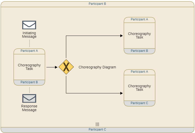
Choreography Diagram
Choreography Diagrams focus on the interactions and communication between different participants in a process.
They show the sequence of messages exchanged between participants and the order of their activities in the process.
Choreography Diagrams are useful for representing the coordination and synchronisation of activities among different participants.
To a certain degree, Choreography Diagrams can be seen as a higher level view of the Collaboration Diagrams.
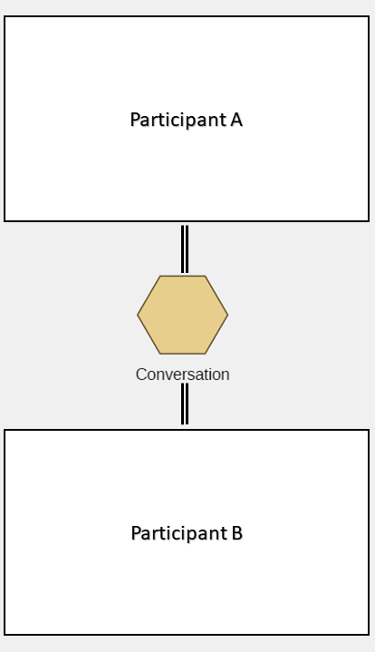
Conversation Diagram
Conversation Diagrams provide a high-level view of message-based interactions between multiple participants.
They show how conversations between participants are organised, including their messages and responses.
Conversation diagrams are particularly helpful for understanding the overall communication flow in complex collaborations.
Each of these diagram types of BPMN serves a specific purpose and provides a standardised and visual representation of different aspects of business processes, making it easier for stakeholders to understand, analyse, and communicate process workflows effectively. Business Process Diagrams and Collaboration Diagrams are widely used, while Conversation Diagrams and Choreography Diagrams are not as commonly represented. ADONIS supports the four types of BPMN diagrams and more - ADONIS fully conforms to the BPMN standard as described in the BPMN Specification - Process Modelling Conformance, Process Execution Conformance, BPEL Process Execution Conformance and Choreography Conformance.
ADONIS supports BPMN DI - BPMN Data Interchange - which provides a mechanism for importing and exporting process diagrams as BPMN files (XML based), while keeping the process content and layout intact. This effectively facilitates interchange of processes between different modelling tools. It covers the interchange of Business Process Diagrams and the Collaboration Diagrams.
BPMN Core Process Elements
When creating business process models using BPMN (Business Process Model and Notation), it is essential to adhere to the process modelling conformance type set. This set defines the elements that must be included in Collaboration Diagrams and Process Diagrams to ensure a comprehensive and standardised representation of business processes. Let's explore the key elements covered in the process modelling conformance type set:
| Element | Description |
|---|---|
| Task (Activity): Tasks represent the various activities and actions performed within the process. BPMN supports different task types, including user tasks, service tasks, script tasks, and more, each serving specific purposes in the process. | |
| Subprocess: Subprocesses are used to represent a group of activities within the main process. Embedded Subprocesses help simplify complex models by breaking them into manageable segments. | |
| Gateway: Gateways are decision points that determine the flow of the process. BPMN supports different gateway types, such as Exclusive Gateways, Parallel Gateways, and Inclusive Gateways, each influencing the path the process takes. | |
| Event: Events represent points in the process that trigger specific actions. There are three types of events: Start Events initiate the process, Intermediate Events occur during the process, and End Events mark its completion. | |
| Participants: Represented with a Pool element, participants are the entities or roles involved in a collaborative process. They help define the interaction and responsibilities of different participants. | |
| Lane: Lanes are visual partitions used in diagrams to group and organise activities within a Pool. They help differentiate the responsibilities of different participants. | |
| Data Object: Data objects represent data used in the process. Data Input and Data Output elements are used to define input and output data associated with Tasks. | |
| Message: Messages represent the communication exchanged between participants in a collaborative process. They facilitate message flow and information exchange. | |
| Group: Groups are used for visual organisation and grouping of related elements in the diagram, enhancing its clarity. | |
| Text Annotation: Text Annotations provide additional information or comments to explain parts of the process, improving its comprehensibility. | |
| Sequence Flow: Sequence Flows define the logical flow of activities and decisions in the process, including conditional and default flows. | |
| Message Flow: Message Flows represent the flow of messages between participants in a Collaboration Diagram, showing the communication pattern. | |
 | Markers: Markers are special symbols like Loop, Multi-Instance, and Compensation used for Tasks and Subprocesses. They provide additional information about the behaviour of these elements. |
| Association: Association elements are used to associate additional information with elements, including Compensation Association or Data Association. When Data Association is "executed", data is copied to the target |
By including these elements in your BPMN diagrams, you ensure a clear, consistent, and standardised representation of your business processes. This conformance type set allows stakeholders to understand and communicate process workflows effectively, leading to better decision-making and process optimisation.
We will use an example organisation, as described below, to go through the core elements of BPMN.
Example Scenario - Onboarding of a new employee
The following example will familiarise you with the typical usage of BPMN Elements. We will build a process diagram together, using the newly learned elements.
The onboarding process is a relatively standard process of introducing a new employee to their new position in the company, providing hardware equipment and documenting the success of the onboarding. There are various departments and responsibilities involved.
Pools and Lanes
A Pool represents a high-level participant or organisation involved in the process. It is visually depicted as a rectangular container that encompasses all the Tasks and Lanes associated with that participant. The Pool acts as a grouping mechanism, allowing related Lanes and activities to be organised together, thereby making it easier to understand the role of that participant in the process.
Each Pool in a Business Process Diagram typically corresponds to a separate organisation or department involved in the process. For instance, it can represent a company, a department within the organisation, or an external partner collaborating in the business process, which is represented with a black box pool. More on that below. By using Pools, the diagram provides a clear and structured view of how different participants are engaged and interact in the overall process flow.
Additionally, within a Pool, Lanes further categorise and partition the Ttasks based on different roles or responsibilities of the participants. Lanes are visually depicted as vertical columns within the Pool, and each Lane is typically labelled with a name that describes the role or responsibility of the participants or department it represents. This naming helps to clearly identify and differentiate the tasks performed by different entities within the same Pool, enhancing the clarity and readability of the diagram.
Example Scenario - Onboarding of a new employee
Let's start with the boundaries of our process. Imagine an onboarding process in the Division A.
Think of all of the departments that are involved in the process. It is a standard HR process, so we are definitely including HR. To provide equipment, we would usually ask the IT department or system administrators. Of course, everyone has a superior, so we should include one. Let's model together:
Events
An Event is an occurrence that marks a significant change in the state of a process. Events can be either internal or external to the process. Internal events are caused by activities within the process, while external events are caused by factors outside the process. For example, a start of a process is marked with an event, a message that comes in the middle of a process can be an event and also the end of a process is an event by itself, and marked as such in BPMN. Essentially, it encapsulates the concept of marking an event that impacts a process in a certain way.
As described above, there are three main types of Events - Start Events, Intermediate Events and End Events.
A Start Event is a special type of event that triggers a process. It is represented by a circle with a thin outline and an open centre so markers can be placed.
Start Events can be triggered by a variety of things, such as:
- A manual action, for example a user clicking a button.
- A message from another system.
- The expiration of a timer.
- The occurrence of a certain condition.
Intermediate Events occur during the execution of a process. They are represented by a circle with a double line and an open centre so markers can be placed.
Intermediate Events can be used to handle things like errors, approvals, or notifications.
The type of trigger that an Intermediate Event can respond to is indicated by the symbol in the middle of the circle. For example, an Intermediate Event with a message symbol in the middle indicates that the event is triggered by a message from another system. BPMN allows for different placement of Intermediate Events, which changes their meaning. There are intermediate sequence flow events and interim attached events. The latter is attached to an activity and is used to capture data and similar actions, while the event attached to the Sequence Flow is used to control the flow of execution in a process.
End Events mark the end of a process. They are represented by a circle with a thick outline and an open centre so markers can be placed.
End Events are activated by a variety of things, such as:
- The completion of all activities in the process.
- The fulfilment of a condition.
- The cancellation of the process.
End Events are throwing types, so they can also execute actions such as sending a message or a signal, this is indicated by the symbol in the middle of the circle. For example, an End Event with a message symbol in the middle indicates that the event sends a message.
Below, under BPMN Elements - Extended you can learn more about all event types.
Task (Activity)
Tasks (Activities) play a pivotal role in modelling business processes. An activity is a generic term used to describe the work that an organisation performs as part of its processes. It encompasses various actions and operations executed to achieve specific objectives within the workflow. Activities can be further categorised into two types: atomic and non-atomic.
A Task represents an example of an atomic activity within the process flow. Atomic activities are indivisible and cannot be broken down into smaller sub-components. Tasks are fundamental building blocks in BPMN, representing a single unit of work that requires no further decomposition. For instance, "Submit Purchase Order" or "Approve Invoice" can be considered as individual Tasks in a procurement process. Tasks are the granular elements that contribute to the overall process execution, providing a clear and well-defined depiction of the process steps.
On the other hand, non-atomic activities involve more complex work that can be decomposed into smaller sub-activities or Subprocesses. Non-atomic activities may encompass multiple steps or decision points, and they may involve interactions with external systems or participants. Such activities can be represented using BPMN elements like Subprocesses, which allow the detailed modelling and organisation of a series of related tasks.
By distinguishing between atomic and non-atomic activities, BPMN 2.0 provides the flexibility to model processes of varying complexity, enabling organsations to represent both simple and intricate workflows with clarity and precision.
Connectors
Connectors are the lines that connect different elements in a BPMN diagram. They are used to show the flow of control between activities, events, and other elements.
There are two main types of connectors in BPMN:
- Sequence Flows show the sequential order of activities in a process. They MUST NOT cross Pool boundaries. They are represented by solid lines with arrows.
- Message Flows show the flow of information between activities. Message flows are NOT allowed within a Pool. They must cross pool boundaries. They are represented by dashed lines with arrows.
Example Scenario - Onboarding of a new employee
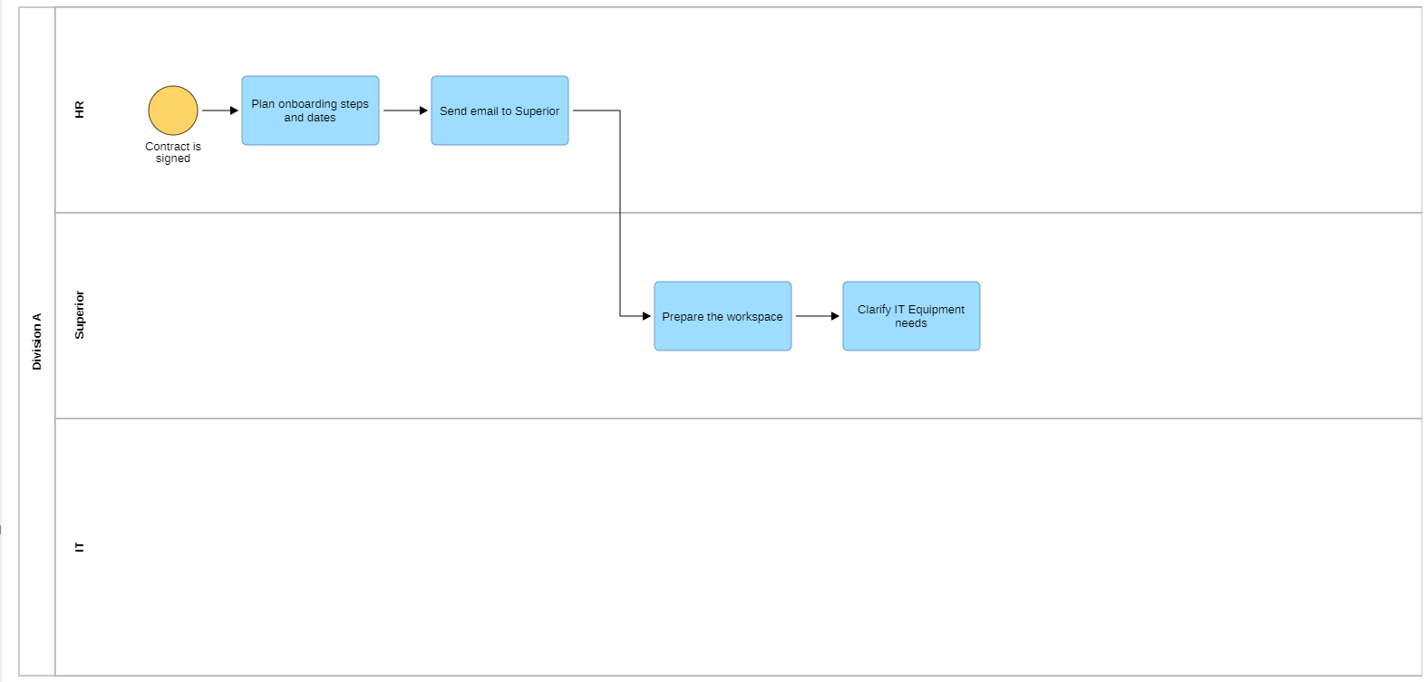
You will need a an event that starts the process of onboarding of a new employee. Most often it is the signature of the contract that starts the process. For this we use the Start Event and label/name it with "Contract is signed". The first task for the HR is to plan the onboarding steps and dates, followed by informing the superior of the new employee. The superior should prepare the workspace and clarify the IT equipment needs of the new employee. Now the process has one Start Event and four Tasks across two Lanes.
Gateways
Gateways are elements in BPMN that are used to control the flow of execution in a process. They are represented by a diamond shape with a number of incoming and outgoing connectors.
The most common types of gateways in BPMN are:
- Exclusive Gateways (XOR): This type of gateway allows only one of the outgoing connectors to be followed. The gateway is configured with a condition that must be met in order for one of the outgoing connectors to be enabled. It can be used to make a decision, such as whether to approve or reject a request. It is possible to use an Exclusive Gateway symbol without an "X" in the middle to denote a split in the process path (see example scenario).
Example Scenario - Onboarding of a new employee
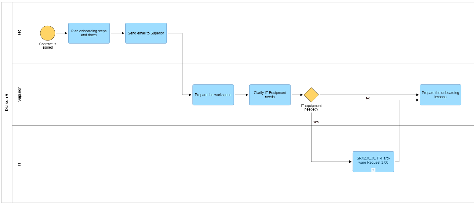
Some employees need specific IT equipment, some don't. The role of the superior here is to decide if they need help from the IT department in sourcing the IT equipment. To come back to theory for a second here - the decision is not being made on the gateway, it is done in the activity before.
In our case either the new colleague needs the equipment or not, so we need to use an XOR Gateway. We also model the next steps, depending on the path taken. If the equipment is needed, the IT department has a process in place to supply equipment. We add the subprocess and link back to the next step, once the subprocess is done.
Keep in mind that the XOR Gateway needs to be labelled with a simple question (ideally one that can be answered with Yes/No). The outgoing flows need to be labelled accordingly. You may or may not use a closing gateway to merge the incoming flows - in ADONIS this is not necessary. Keep in mind that we will finish the process later, once we have gone through important aspects of BPMN extensions.
Parallel Gateways (AND): This type of gateway allows all of the outgoing connectors to be followed. The gateway is not configured with a condition, so all of the outgoing connectors are enabled when the gateway is activated. It can be used to execute multiple activities in parallel, such as when multiple people need to approve a request.
Example - Parallel Gateway
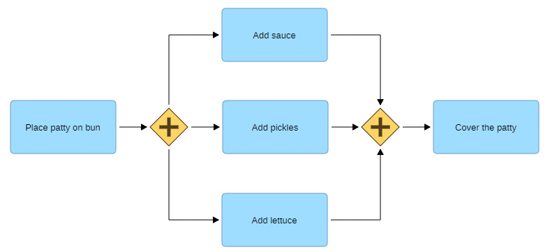
For example, let's think of a part of a process of preparing a hamburger with all ingredients.
In this case we model a Parallel Gateway and the preparation is only done when all ingredients are placed on the burger. It doesn't matter which ingredients are placed first or if the persons place the ingredients at once, the process can only continue when all activites are done.
Inclusive Gateways (OR): This type of gateway allows any of the outgoing connectors to be followed. It's somewhat akin to a blend of XOR and AND gateways. If the Sequence Flow after the gateway is not configured with a condition, this connector is enabled by default when the gateway is activated. If there is a condition, the process follows this path (and the path without condition) as long as the condition is met. It can be used to allow multiple paths of execution, such as when there are multiple ways to complete a task.
Example - Inclusive Gateway
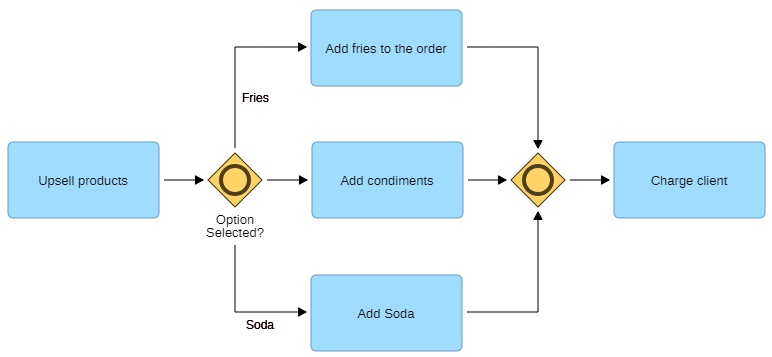
In this case we model an inclusive gateway. Condiments are always given so the flow after the gateway has no condition, while the other two are based on customer choice. The one without the condition acts as an AND gateway. Afterwards the paths merge, and the process cannot continue until the non-conditioned path is done.
BPMN Fit for Business - BOC Group Best Practice
The BPMN Fit for Business approach developed by the BOC Group is a result of over 25 years of experience in best-practice BPMN methodologies. Rooted in practical insights, this approach aims to bridge the gap between theoretical BPMN constructs and the real-world requirements of businesses. This chapter delves into the key principles and insights of the BPMN Fit for Business approach, as outlined in the "BPMN 2.0 Handbook" by Shapiro et al (2011), particularly the chapter titled "BPMN For Business Professionals: Making BPMN 2.0 Fit for Full Business Use."
Use Case Scenarios: The BPMN Fit for Business approach centres around addressing critical business needs through BPMN-based modelling. Several use case scenarios have been identified as prime candidates for this approach:
- Organisational Analysis and Work Instructions: BPMN is utilised to map and analyse organisational processes, providing a clear understanding of roles, responsibilities, and interactions.
- Building an Internal Control System (ICS): The approach assists in defining and visualising internal control processes, helping organsations ensure compliance and risk management.
- Enterprise Risk Management: Extended BPMN facilitates the modelling of risk management processes, enabling organsations to identify, assess, and mitigate risks effectively.
- Process Costing: The extended metamodel helps in evaluating process costs, enabling informed decision-making related to resource allocation and process optimisation.
- Simulation: Utilising these extensions for simulation purposes allows organsations to predict process behaviour under different conditions, aiding in process improvement strategies.
- Test-Case Management: BOC's metamodel can be employed to map out test-case management processes, enhancing testing efficiency and accuracy.
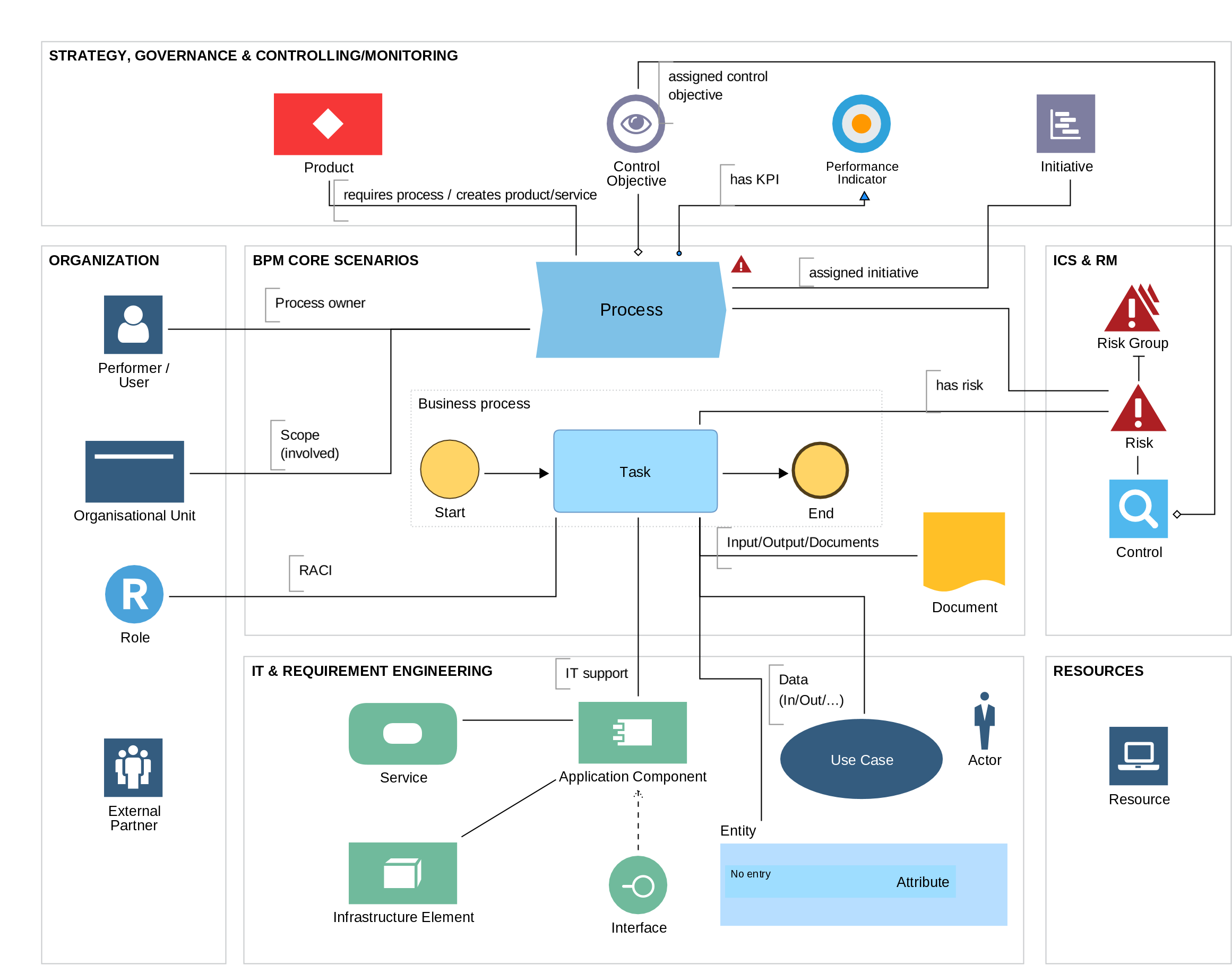
The ADONIS BPMN Fit for Business Metamodel shows all of the extensions of the standard BPMN metamodel that enable documentation of real-life use cases in Business Process Management.
Process Mapping and Landscape
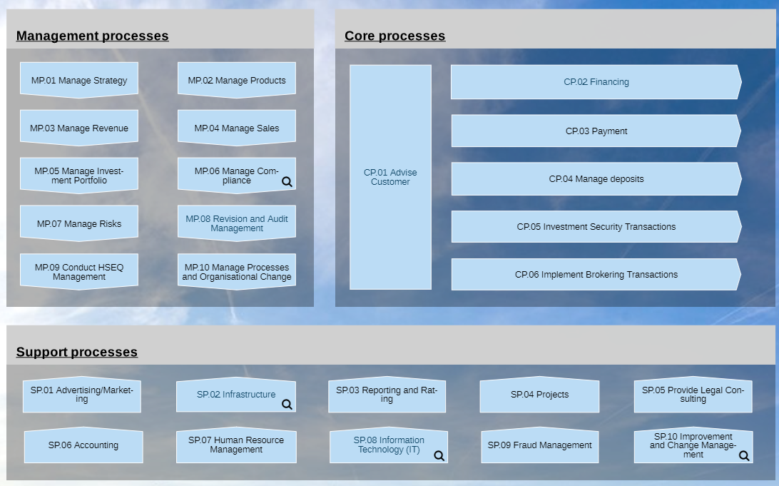
An essential starting point for the BPMN Fit for Business approach is the creation of a comprehensive process map or Process Landscape. This map serves multiple purposes:
- Process Identification and Classification: The process map helps identify and categorise processes, allowing organsations to classify them into management, core, and supporting processes.
- Scope Definition: The process map defines clear boundaries and scopes for various processes, ensuring a structured approach to BPM initiatives.
- Common Understanding: The process map fosters a shared understanding of an organisation's processes, aiding in assigning ownership, comprehending end-to-end processes, and establishing interfaces.
- Alignment: Process maps help align BPM initiatives with organisational goals and strategies, ensuring that efforts contribute directly to business success.
Beyond BPMN Elements
While BPMN offers a robust framework for process modelling, there are certain business-specific elements that BPMN lacks. BPMN Fit for Business approach bridges these gaps:
- Process Owners: The approach incorporates process owner identification as well as responsibilities for carrying out the individual steps in a processes (according to RACI principle). This significantly improves process transparency and allows for tracing accountability
- Inputs and Outputs: With BPMN Fit for business it is possible to associate inputs and outputs to processes as a whole, and to specific activities (tasks) within the process. This enables variety of analyses of organization's documents. Within ADONIS, it is also possible to link applicable documents.
- Connected IT Systems: Integration of BPMN with IT systems is mapped, ensuring a seamless connection between business processes and technological implementations.
- Process Performance Indicators: The approach integrates process performance metrics into BPMN models, facilitating process monitoring, analysis, and improvement.
- Risks and Controls: The BPMN models include risk assessments and control mechanisms, enabling evaluation and management of risks.
- Attributes for Time and Cost: BPMN models are enriched with attributes for time and cost, providing insights into process efficiency and resource requirements.
With simple graphical changes, this information can be immediately visible to readers of business process diagrams, see below:
By blending robust BPMN constructs with additional business-centric elements, this approach enables organsations to create models that are not only accurate but also highly relevant and actionable. The emphasis on process mapping, alignment with organisational goals, and integration with IT systems ensures that BPMN models are not just static representations but dynamic tools for driving business success.
Internal Control Systems
The BPMN Fit for Business approach integrates the Process-Risk-Control framework, vital for effective ICS implementation.
In the context of BPMN:
- Risk and Control Objects: Specific objects for risks and controls are created within the BPMN model, ensuring robust risk management.
- Enhanced BPMN Tasks: Traditional BPMN tasks are extended with attributes to capture risks and assign controls. This documentation ensures comprehensive risk mitigation.
BPMN Integration for ICS:
- Risk Identification: Risks associated with each process step are identified and linked to BPMN tasks, promoting proactive risk management.
- Control Documentation: Controls are detailed within BPMN tasks, offering insights into risk-mitigation measures.
- Collaborative Efficiency: The extended BPMN framework supports parallel task execution and effective collaboration among stakeholders.
The incorporation of ICS principles within the BPMN Fit for Business approach transforms conventional BPMN models into dynamic tools for managing complex ICS projects.
Process Simulation and Cost Calculation
The quantitative and dynamic assessment of business processes, encompassing roles, units, products, and resources, is pivotal for informed management decisions. This evaluation gains utmost importance before process implementation or organisational changes. Employing process costing and simulation algorithms aid in achieving this analysis.
The BPMN 2.0 specification lacks the necessary details to address these analyses. Therefore, the following parameters are used for extension:
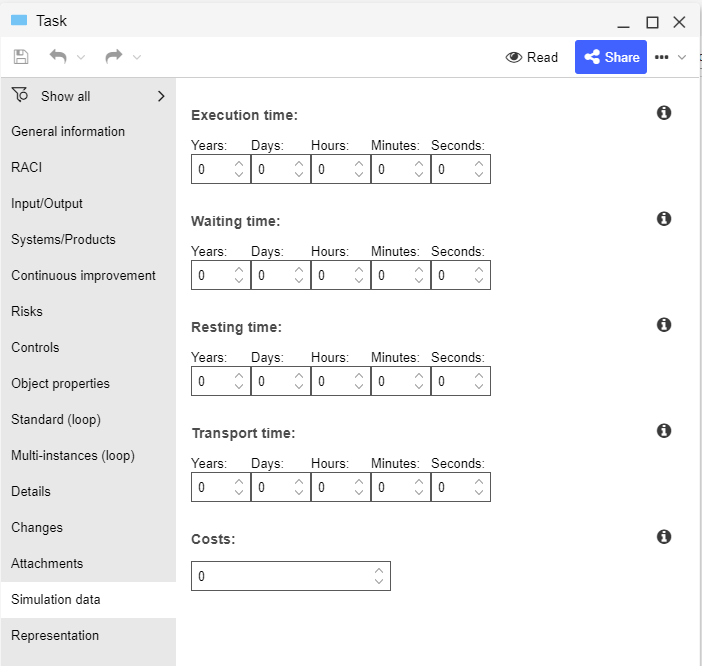
Time-Related Parameters
- Execution Time: Time required for Task execution.
- Waiting Time: Time before Task execution or during interruptions.
- Resting Time: Time post Task execution but pre-transport.
- Transport Time: Time for material movement between Tasks.
These can be stored on the Task level in ADONIS. All attributes that need to be considered can be found in the Notebook chapter "Simulation data".
Cost-Related Parameters
- Fixed Activity Costs: Directly tied to Tasks, irrespective of the actor executing.
- Actor-Related Costs: Costs linked to specific Task execution by actors.
- Resource Costs: Arise from resource requirements for Task execution.
- Process Costs: Sum of all directly assignable and computed costs for a specific process.
Capacity-Related Parameters
- Process Quantity: Frequency of process execution in a defined period.
- Resource Need: Quantity of resources (e.g., human or technical) required per process execution.
- Workload: Resource involvement or requirement for process execution or handling.
Other Parameters
- Probabilities: For scenarios with control or information flow branching into alternatives.
- Statistical Distributions: Potential inclusion of statistical distributions like discrete, normal, uniform, or exponential, especially in advanced contexts.
Incorporating process simulation and cost calculation within the BPMN Fit for Business approach enriches the ability to make well-informed decisions.
Summary
Incorporating the BPMN Fit for Business approach by BOC Group revolutionises process modelling by addressing real-world challenges. By bridging theoretical BPMN constructs with practical business needs, this approach enhances collaboration and decision-making. It accommodates intricate scenarios, such as Internal Control System projects, by integrating risk and control elements seamlessly. Moreover, it empowers organsations to evaluate processes quantitatively through simulation and cost analysis, fostering informed decisions. The BPMN Fit for Business approach serves as a dynamic compass for businesses navigating the complexities of process management, aligning modelling with strategic goals.
BPMN and Modelling in ADONIS
In the chapter BPMN Core Process Elements, you learned about the main elements used in BPMN. These elements, aligning with BOC best practices, encompass approximately 95% of the scenarios for modeling with BPMN. ADONIS, of course, fully supports all BPMN modelling elements.
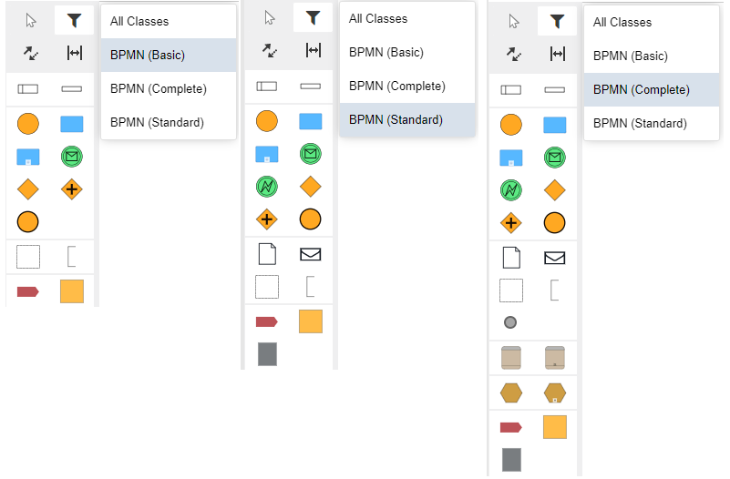
In the chapter BPMN Fit for Business - BOC Group Best Practice, we delved into the ADONIS extensions of the BPMN metamodel, enabling the capture of a wide spectrum of BPM requirements that modern organisations may encounter.
Additionally, towards the end of this document in the section BPMN Elements - Extended, you'll find detailed insights into different types of BPMN objects, complete with guidance on their appropriate usage.
First, though, let's explore some essential rules and best practices for effective BPMN modelling, particularly within the ADONIS environment.
Scope, Purpose and Depth of the Process Detail
Begin by clearly defining the scope and purpose of your BPMN diagram. Identify the specific business process you're modelling and the goals you aim to achieve with the diagram. Also keep in mind what level of detail is needed to successfully read and then execute this process. Use objects such as Subprocesses which allow for maintaining clarity while still holding information, just a level deeper.
Responsibilities and Roles
Utilise Pools to represent different organsations or departments involved in the process. Within each Pool, use Lanes to denote various roles or responsibilities. This visually structures the diagram and clarifies interactions.
Objects
Place the Start Event to signify the process initiation trigger.
Incorporate activities within appropriate swimlanes.
- These activities encompass the steps performed in the process, which can range from manual to automated actions.
Insert gateways to manage process flow.
- They can split, merge, or make decisions within the process.
Events, which can occur anywhere, trigger actions or alter the process trajectory.
Label all elements with concise, meaningful names.
- Clear labeling enhances understanding and prevents confusion among stakeholders.
Element Type Labeling format Task
Best practice suggests that a verb+object naming convention is used to describe the performed action. E.g. "Store goods" or "Send Invoice" Gateway
Exclusive Gateways should be labeled with a question, preferably a simple Yes/No question, and the question should be phrased such that the answer "Yes" is the most common path. Hence, the Sequence flows after the Gateway should be labeled with the answer to the question (Preferably, Yes/No).
Inclusive Gateways should be labeled with a question as well. It is important that the Sequence flowsare labeled with answers to the question, and if there is a path that is unconditional, this one shouldn't be labeled.
Parallel Gateways do not need to be labeled, as there are no intrinsic condition behind them, but rather each path is traversed.Event
Events should be labeled such that they describe the state reached. Best practice suggests using verbs in past participle - E.g. "Contract signed", "Employee onboarded" etc. - for Start, End and Intermediate events.
Visual impression
- Try to use a single Start Event for clarity.
- Maintain horizontal alignment of activities within their respective swimlanes.
- Clearly label Pools and Lanes with descriptive names for easy identification.
- Arrange connectors such as Sequence Flows to minimise intersections. This ensures a clean and organised diagram layout.
- Sequence Flows should follow a logical direction from the source to the target element. Avoid crisscrossing flows, as it may confuse readers.
- Overcomplicating gateways can make the diagram hard to understand. Opt for simplicity unless complexity is necessary.
- Maintain consistent sizing of symbols throughout the diagram. This uniformity contributes to a visually balanced presentation.
Validate against rules
When creating a BPMN diagram, there are a number of rules that must be adhered to ensure that the diagram is clear, concise, and easy to understand. To ensure this, ADONIS includes a validation engine that verifies compliance with BPMN rules and best modelling practices, and provides guidance to address any issues. Learn more about validation in ADONIS in the ADONIS User Manual.
Example Scenario - Onboarding of a new employee
We have modelled several steps and added a decision point and now we need the final activities before the process end. However, as emphasised in the preceding chapter, simply modelling the process is not necessarily enough to cover the business needs for process documentation and modelling.
We need to add the responsible roles, we need to assign used IT systems, assign activity types and more. This is all in the name of transparency and clarity for the end process reader. Here is a sample solution:

To learn more about modelling in ADONIS, go to the ADONIS User Manual.
BPMN Elements - Extended
Pools and Lanes
Handling Unknown Process Details and External Interactions
Pools act as containers for high-level participants or organsations involved in the process, while Lanes provide a sub-partition within the Pool to group Tasks based on specific roles or responsibilities.
By utilising Pools and Lanes, organsations can clearly define the responsibilities of each participant or department in the overall process flow. Each Pool represents a separate organisation or entity, such as a company, department, or external partner. Within each Pool, lanes help categorise Tasks based on the participants' specific functions or departments, providing a visual representation of the division of work. Black box pools are Pools that are not further decomposed into lanes. This can be useful for representing complex or sensitive processes that are not fully understood.
Black box pools are typically used to represent external organsations or entities that are not directly involved in the process being modelled. They can also be used to represent internal processes that are not relevant to the scope of the model.
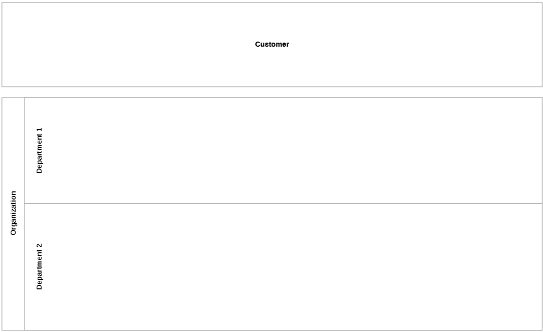
For example, in a procurement process involving multiple departments, each department can be represented as a lane, and various activities related to purchase requisition, approval, and procurement can be organised in separate lanes. This allows stakeholders to understand the distinct responsibilities and contributions of each department, ensuring a streamlined and efficient collaboration. In addition, a black box pool can represent a supplier and allow for modelling the overall process of procuring an order without having to worry about the specific details of the supplier's internal processes.
Task
Task Types
In BPMN 2.0, there are several task types used to represent different types of activities or work performed within a business process.
| Object | Description |
|---|---|
| Represents work that requires human interaction or manual input. User tasks are used to model activities that involve user decisions or actions, like approvals or reviews. | |
| Represents work that is entirely manual and does not involve automation or external systems. Manual tasks are used for activities that must be performed manually by a person without any automated assistance. | |
| Represents work performed by an external service or application. Service tasks are used to model activities that interact with external systems, such as web services or APIs. | |
| Represents work that sends a message to an external participant or system. Send tasks are used to model activities that initiate communication by sending messages. | |
| Represents work that waits for and receives a message from an external participant or system. Receive tasks are used to model activities that wait for incoming messages before proceeding. | |
| Represents work related to evaluating business rules or decision-making logic. Business rule tasks are used for activities that involve making decisions based on predefined rules or conditions. | |
| Represents work that is performed through an automated script or code. Script tasks are used to model activities that are executed using scripts or automated routines. | |
| Represents a reusable sub-process that references another BPMN process. Call activities allow for process modularisation and reusability. |
Events
As mentioned above, there are three main types of events in BPMN:
- Start Events mark the beginning of a process.
- Intermediate Events occur during the execution of a process.
- End Events mark the end of a process.
Of these, the most common types, depicted with the following symbols:
- Message: This symbol indicates that the event is triggered by a message from another system.
- Timer: This symbol indicates that the event is triggered by the expiration of a timer.
- Error: This symbol indicates that the event is triggered by an error condition.
- Signal: This symbol indicates that the event is triggered by a signal from another system.
The following event types are less common, but still important to define:
- Conditional: This symbol indicates that the event is triggered by a condition.
- Escalation: This symbol indicates that the event is triggered by an escalation condition.
- Compensation: This symbol is used to depict undoing of steps that were already successfully completed, because their results and possible side effects are no longer desired and need to be reversed.
- Cancel: This symbol indicates that the process is cancelled.
- Terminate: This symbol indicates that the process is terminated.
- Link: This symbol indicates that the event is used to connect two sections of a process.
Intermediate events can be classified as either catching or throwing. Catching events react to a trigger, while throwing events trigger another event. The symbols in the middle of BPMN event symbols depict the type of event. In addition to the type of event, events can also be classified as either interrupting or non-interrupting.
- Interrupting events suspend the current execution of the process and start the new process instance. This means that the current activity is cancelled, and the process starts over from the interrupting event. Interrupting events are typically used to handle errors or unexpected situations.
- Non-interrupting events do not suspend the current execution of the process. This means that the current activity continues to run while the new process instance is started. Non-interrupting events are typically used to handle things like approvals or notifications that do not need to interrupt the current flow of the process.
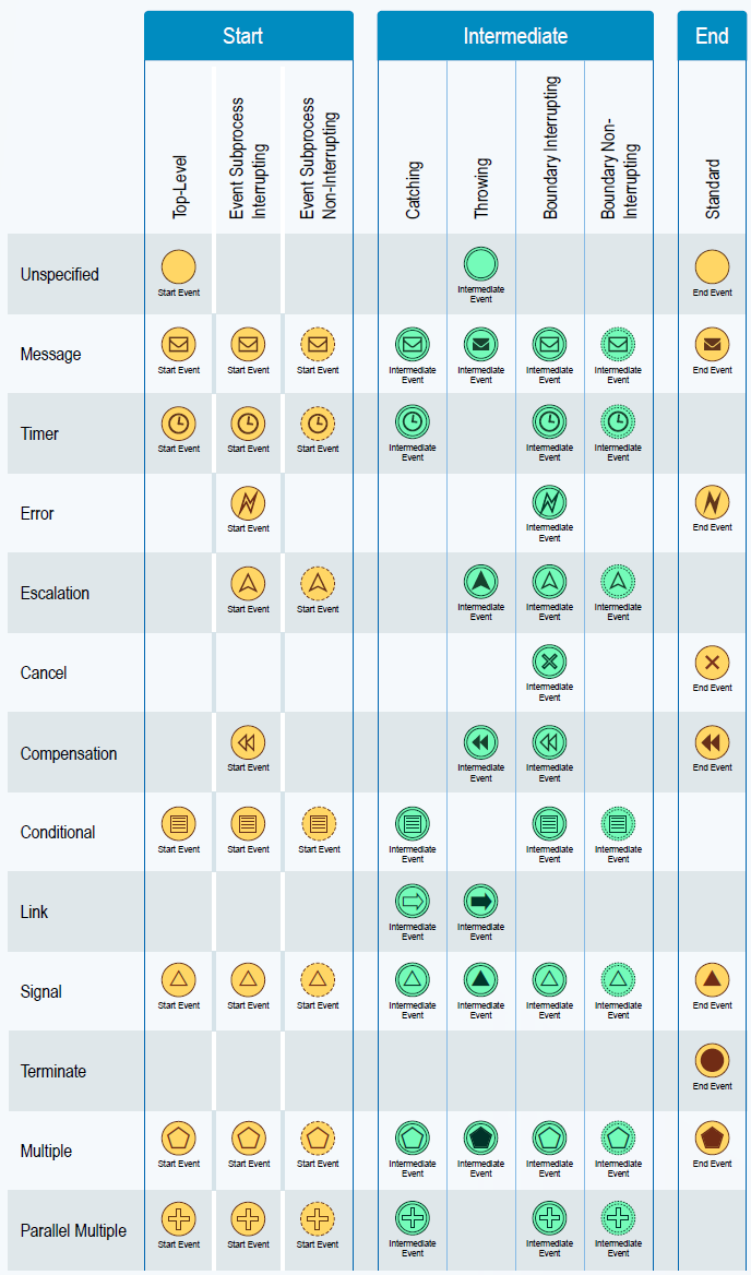
Events are an important part of BPMN and can be used to represent a variety of things that happen during the execution of a process. The type of event and whether it is interrupting or non-interrupting can have a significant impact on the flow of the process.
Connectors
In addition to Sequence Flows and Message Flows mentioned above, there are several other ways to represent the flow of Tasks in BPMN:
- Default Flows are used to specify the default path of execution for a conditional Sequence Flow. They are represented by a dashed line with a black arrowhead. Used after XOR and OR gateways, they resolve conflicts so the process doesn't get "stuck".
- Conditional Flows allow the flow of control to branch depending on a condition. They are represented by a dashed line with a black arrowhead and a condition expression.
The specific types of Sequence Flows that are used in a process will depend on the specific requirements of the process.
- Association Flow: Besides the Sequence Flow and Message Flow, BPMN allows for Association Flows, which connect an activity or event to a non-flow element, such as a Text Annotation. They are represented by dotted lines.
Data Association Flow: Demonstrate how specific process steps utilize data (either Data Objects or Data Stores) by incorporating a Data Association arrow (a dotted line with an arrowhead). Please be aware that tokens do not follow the Data Association – they are not part of the process flow.
When modelling in ADONIS, connectors will be created based on the BPMN rules of connecting objects. E.g. Task will connect with a Data Object only via Data Association Flow and the arrow can be placed based on if the flow is incoming or outgoing from the task. Default flow can be defined in the properties of the Sequence Flow.
Connectors are an important part of BPMN and are used to show the flow of control between different elements in a process. The different types of connectors can be used to represent a variety of different scenarios, such as the sequential execution of activities, the flow of information between activities, and the handling of errors and exceptions. It is not best practice to use more complex flows than Sequence flow and Message Flow as it is hard to read and non-technical users might not recognize them.
Here are some additional things to keep in mind about connectors in BPMN:
- Connectors can be labelled with text to provide additional information about the flow of control.
- Connectors can be annotated with conditions to specify when they are enabled or disabled.
Gateways
In addition to the Exclusive, Inclusive and Parallel gateway types, there are a number of other types of gateways in BPMN. Here's how to differentiate between them:
| Gateway Type | Purpose | Activation | Outgoing connectors | Execution | Symbol |
|---|---|---|---|---|---|
| Exclusive Gateway (XOR) | To make a decision | Enabled by a condition | Only one outgoing connector is enabled | The enabled outgoing connector is followed | |
| Inclusive Gateway (OR) | To allow multiple paths of execution | Can be enabled by a condition (otherwise default flow is taken) | Depending on the condition, 1-to-n outgoing connectors are enabled | Depending on the condition, 1-to-n outgoing connectors are followed | |
| Parallel Gateway (AND) | To execute multiple activities in parallel | Not enabled by a condition | All outgoing connectors are enabled | All outgoing connectors are followed simultaneously | |
| Event Based Gateway | To delay a point where the flow is picked | Enabled by an event | Only one outgoing connector is enabled | The enabled outgoing connector is followed | |
| Event Based Gateway (Instantiate) | To instantiate a process when an event occurs | Enabled by an event | One outgoing connector is enabled | The enabled outgoing connector is used to instantiate the process | |
| Complex Gateway | To allow for more complex routing logic | Enabled by a set of rules | One or more outgoing connectors are enabled | The enabled outgoing connectors are followed | |
| Parallel Event Based Gateway (Instantiate) | To instantiate multiple processes in parallel when an event occurs | Enabled by an event | All outgoing connectors are enabled | The processes are instantiated in parallel |
Conversation Diagrams
Conversation Diagrams are used to group Message Flows and associate correlations for better communication flow and coordination. A Conversation Diagram represents a particular usage of a Collaboration Diagram, in an informal way. Practically, it is a simplified version of the Collaboration Diagram. There are several elements used in Conversation Diagrams:
Conversation Elements (Nodes)
- Conversation
- Call Conversation
- Sub-Conversation
Conversation link: Represented by two parallel lines connecting a pool to a conversation node
Pool: Representing participants in the conversation.