Edit Models
The following sections provide an overview of the functions needed for editing models in the graphical editor.
Open Model
In order to open a model:
- Double-click the model in the Model Catalogue.
The model opens in the graphical editor.
In order to open a model with specific settings, proceed as follows:
Select the model you want to open in the Model Catalogue.
Right-click the model, point to Open, and then click either Model, Text or Table.
The graphical editor ("Model") lets you design, modify and update models. The textual view ("Text") is especially useful to quickly understand the flow of tasks and decisions in a process. The tabular editor ("Table") is ideal for the large-scale editing of attributes.
Search in Model
You can search for objects in the graphical editor.
Execute Search
In order to execute a search in the active model:
Click the More button
 in the
menu bar of the open model, and then click Search in model
in the
menu bar of the open model, and then click Search in model
 .
.Enter the search string into the input field.
As you type, ADONIS NP will start highlighting objects that contain the search string in their name. The first search result will be focused.
Move Focus to the Next Search Result
In order to move the focus to the next search result:
- Press <Enter> or click the Search icon
().
Close Search Box
In order to close the search box:
- Click the icon
 .
.
Cut/Copy/Paste/Delete Objects in the Graphical Editor
The manipulation functions Cut, Copy, Paste and Delete are available in the graphical editor:
Press <Ctrl> + <X> to cut an object.
Press <Ctrl> + <C> to copy an object.
Press <Ctrl> + <V> to paste an object.
Press <Del> to remove an object from the model.
Press <Shift> + <Del> to remove an object from the model and the Object Catalogue.
Special Case: Insert Object between Two Connected Objects
Often it is necessary to insert an object between two connected objects. For this purpose, the graphical editor contains a function that automatically connects the new object to the model structure:
- Click the connector in question when placing the object. When positioned correctly, the connector is highlighted.
ADONIS NP splits the connector up automatically and connects the new object to the neighbouring objects.
Special Case: Delete Object with Incoming and Outgoing Connectors of One Type
When you delete an object that has exactly one incoming and one outgoing connector of one type, a connector is drawn from the preceding object to the following object (auto heal function).
The auto heal function can also be applied to multiple objects at once. When deleting a set of two or more objects with exactly one incoming and one outgoing connector of one type and connectors of the same type running through the set, a connector from the previous to the following object is drawn.
Connector Functions
The following sections provide an overview of the functions needed for editing connectors.
Model Bendpoints
Connectors can be modelled with any number of bendpoints. In order to do this, proceed as follows:
- When drawing a connector, click consecutively on all free spaces of the drawing area where you want the connector to bend.
Create New Bendpoint
Click on the connector at any free spot.
Drag it into a new position.
If rectangular connectors are enabled, this function is not available.
Move Bendpoint
Click on the bendpoint.
Drag it into a new position.
If rectangular connectors are enabled, this function is not available.
Delete Bendpoint
Drag the bendpoint to a place where the two adjacent connector lines form a straight line. As soon as the mouse button is released, the bendpoint is deleted.
As an alternative, select only the bendpoint and press <Del>.
If rectangular connectors are enabled, this function is not available.
Merge Multiple Bendpoints
- Drag one of two bendpoints over the other.
If rectangular connectors are enabled, this function is not available.
Parallel Translation of Connectors
Horizontally or vertically drawn straight connectors can be moved as a whole:
Select the connector.
Move it in parallel by drag and drop.
You can also move individual segments of rectangular connectors in this manner.
Reallocate Connector
Select the connection point.
Drag it to the new object.
Delete Connector
Unnecessary connectors can be easily deleted.
Select the connector (click an area of the connector edge without a bendpoint) and press <Del>.
As an alternative, from the context menu of the connector, select Delete.
Align Objects
ADONIS NP allows you to automatically align objects in the graphical editor. In order to do so:
Select the objects you want to align.
Right-click the objects, point to Align, and then select an alignment option.
Additionally, you can align all objects within a container object (e.g. a Pool or Lane).
- Right-click the container object, point to Align, and then select an alignment option.
Alignment Options
The following alignment options are available:
Center vertically
Align the objects vertically
Center horizontally
Align the objects horizontally
Distribute horizontally
Evenly distribute the objects horizontally
Distribute vertically
Evenly distribute the objects vertically
Align right
Align the right side of the objects with the right edge of the right-most object
Align left
Align the left side of the objects with the left edge of the left-most object
Align top
Align the top side of the selected objects with the top edge of the top-most object
Align bottom
Align the bottom side of the selected objects with the bottom edge of the bottom-most object
Change Modelling Direction: Vertical/Horizontal
The modelling direction can be set to horizontal (modelling is done from left to right) or vertical (modelling is done from top to bottom).
The default modelling direction for each model type is defined in the Administration Toolkit.
You can change the modelling direction for a specific model in the graphical editor. The objects on the drawing area are automatically rearranged.
The following options are available:
Change Direction: Vertical
To place the objects in the model from top to bottom instead of from left to right:
- Click the More button in the
menu bar of the open model, and then click Change direction: vertical.
Change Direction: Horizontal
To place the objects in the model from left to right instead of from top to bottom:
- Click the More button in the
menu bar of the open model, and then click Change direction: horizontal.
When using the Hover Modelling Assistant, the modelling direction determines where the next object is placed:
Horizontal: To the right of the selected object
Vertical: Below the selected object
Number Objects
ADONIS NP allows you to automatically assign numbers to the objects in a model. The following options are available:
Number Objects Horizontally
In order to number all objects in the model from left to right:
Right-click in the drawing area to open the context menu.
Select Number objects - Horizontal.
Number Objects Vertically
In order to number all objects in the model from top to bottom:
Right-click in the drawing area to open the context menu.
Select Number objects - Vertical.
Remove Object Numbering
In order to remove all numbers from the model:
Right-click in the drawing area to open the context menu.
Select Number objects - Remove object numbering.
Depending on the Application Library, different model types may be considered for numbering. In the ADONIS BPMS Application Library, this functionality is activated for Process Landscapes, Business Process Diagrams, Choreography Diagrams and Working Environment Models.
Check Spelling
ADONIS NP can look for and correct misspelled words in text fields. Spell checking is available, for example, when editing text attributes, in search boxes, during translation etc. Misspelled words are marked with a wavy line.
In order to correct a misspelling:
- Right-click the misspelled word, and then replace it with a suggested word from the list.
This feature uses native spell checking capabilities provided by the browser. Spell checking is available in Internet Explorer 11, Microsoft Edge, Mozilla Firefox, Google Chrome and Safari.
You can configure your browser to support multiple languages if desired. To find out how to install additional languages, please refer to the browser documentation.
Add/Remove Empty Space
In the graphical editor, you can add or remove any size of empty space between objects. In order to do so:
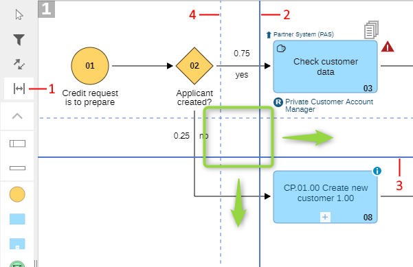
Click the Add/Remove empty space button
 at the top of the modelling
bar (1).
at the top of the modelling
bar (1).Click the desired location of the drawing area (= where you want to add or remove space).
Now do one of the following:
Insert Horizontal Empty Space
Drag the bold vertical line (2) to the right (→). When you release the mouse button, all objects that were located to the right of the original position will be moved further to the right.
Insert Vertical Empty Space
Drag the bold horizontal line (3) down (↓). When you release the mouse button, all objects that were located below the original position will be moved further down.
Remove Horizontal Empty Space
Drag the bold vertical line to the left (←). A dashed line indicates the border of the area that can be removed (4). When you release the mouse button, all objects that were located to the right of the original position will be moved further to the left.
Remove Vertical Empty Space
Drag the bold horizontal line up (↑). A dashed line indicates the border of the area that can be removed. When you release the mouse button, all objects that were located below the original position will be moved further up.
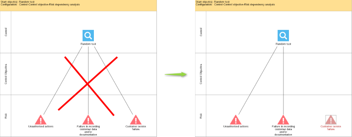
Update All Relations
In the graphical editor, relations between repository objects are often represented as connectors. This applies to models that you have created yourself, but also to views that you have saved as a model etc.
When you modify these relations in the Notebook of an object, the model may contain incorrect or outdated information. In order to update relations:
Open the model in the graphical editor.
Do one of the following:
To update all relations in the model, click the More button
in the menu bar of the
open model, and then click All objects: update all relations.To update relations of specific objects, right-click the objects, and then click Selected objects: update all relations.
Outdated connectors are removed (= the relation has been deleted from the Notebook) and new connectors are drawn (= a new relation has been created in the Notebook).
Example
Assign Responsibilities to Tasks
This function can be used to transfer references of container objects (objects that are used to contain other objects) to the objects placed on these container objects. Specifically, you can transfer responsibilities from Lanes to the Tasks they contain.
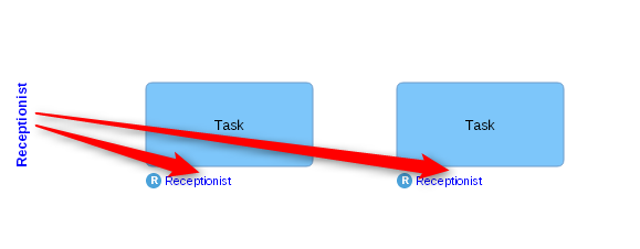
The reference must be of the type Resource (attribute in the Notebook chapter General information of the Lane). In the contained Tasks, the reference is assigned to the attribute Responsible for execution (attribute in the Notebook chapter RACI).
In order to assign a resource:
Select a Lane on the drawing area.
Right-click the Lane, and then click Assign responsibilities to tasks
 .
.
The reference is simultaneously assigned to all Tasks on the Lane.
If the reference cannot be transferred because the source attribute and target attribute are not of the same type or if any other error occurs, a message window is displayed.