Model and Connect Objects
The following sections provide an overview of the most important functions for adding and connecting objects in the graphical editor.
Create Objects in the Graphical Editor
To create objects in the graphical editor, you can do the following:
Create objects manually by selecting them in the modelling bar and placing them where you want to or:
Once you have created the first object in a model manually, use the Hover Modelling Assistant to automatically place additional objects on the drawing area.
This scenario particularly applies to modelling objects. Repository objects can also be created directly in the Object Catalogue.
Create Objects Manually
In order to create objects manually, proceed as follows:
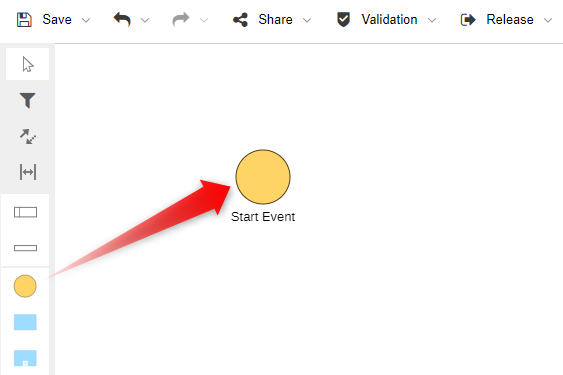
Select an object in the modelling bar, and drag it onto the drawing area, or click where you want to add the object.
Enter a name for the object.
Create Objects Using the Hover Modelling Assistant
The Hover Modelling Assistant helps speed up the modelling process. Depending on the currently selected object, it suggests which objects should be added next.
The Hover Modelling Assistant is available in Business Process Diagrams, Conversation Diagrams and Choreography Diagrams.
In order to use the modelling assistant:
- Create a new object manually or select an object you have previously created. When you do that, the modelling assistant appears.
If the modelling assistant does not appear, it may be disabled. For details on how to adapt your personal settings, please refer to the section Modelling.
Now do one of the following:
Place Object Automatically
Click the object you want to add to the model and enter a name. To see additional object choices, click the More button
 , and then select an object from
the menu that appears.
, and then select an object from
the menu that appears.The new object is placed on the drawing area close to the original object. A connector linking both objects is also created. Flow objects are placed in the modelling direction, while all other objects are placed perpendicular to the modelling direction.
Place Object Manually
Drag the object you want to add to the desired location on the drawing area. When you release the mouse button, the new object is created, and the appropriate connector linking both objects is also created. This is useful e.g. when you model decisions in a process flow and create alternative process flows.
Insert Object between Two Connected Objects
Select the object after which you want to insert the new object, and then click the object you want to add to the model. ADONIS NP splits the connector up automatically and connects the new object to the neighbouring objects.
The type of connector that is drawn between objects by the modelling assistant is determined automatically.
Connect Objects
To draw a connector between two objects, choose one of the following options:
Draw Connector Manually
In order to draw a connector manually:
Click the Create relation icon
 at the top of the modelling
bar.
at the top of the modelling
bar.Click the object the connector should start from.
Click the target object.
Draw Connector Using the Hover Modelling Assistant
In order to draw a connector using the modelling assistant:
Select the object the connector should start from. When you do that, the modelling assistant appears.
Select the Create relation icon
 , and drag it onto the target
object, or click the target object.
, and drag it onto the target
object, or click the target object.
If the modelling assistant does not appear, it may be disabled. For details on how to adapt your personal settings, please refer to the section Modelling.
For every connector type only certain object types are defined where it may begin or end. When drawing a connector, ADONIS NP instantly checks whether and how the “from and to” objects can be connected. The following cases can occur:
One Type of Connector Matches "from and to" Objects
The connector is drawn.
Several Types of Connectors Match "from and to" Objects
A support dialogue opens. All valid connector types for incoming and outgoing connectors are listed as sub items. Choose the desired connector type.
Target Object Invalid for Connector
The connector cannot be created.
Rectangular Connectors vs. Straight Connectors
By default, ADONIS NP draws right-angled connectors
![]() . If you prefer, you can make
ADONIS NP draw straight connectors
. If you prefer, you can make
ADONIS NP draw straight connectors
![]() . For details on how to adapt your
personal settings, please refer to the section Modelling .
. For details on how to adapt your
personal settings, please refer to the section Modelling .
Connector not Visible if One Object Contains the Other
Objects can be placed on top of each other so that one object contains the other. If such objects are linked with a connector, it is automatically hidden when you drop one object inside the other.
Create Relations Using Drag-and-Drop Operations in the Graphical Editor
In the graphical editor, there are multiple ways to create relations by drag and drop. The following functions are available:
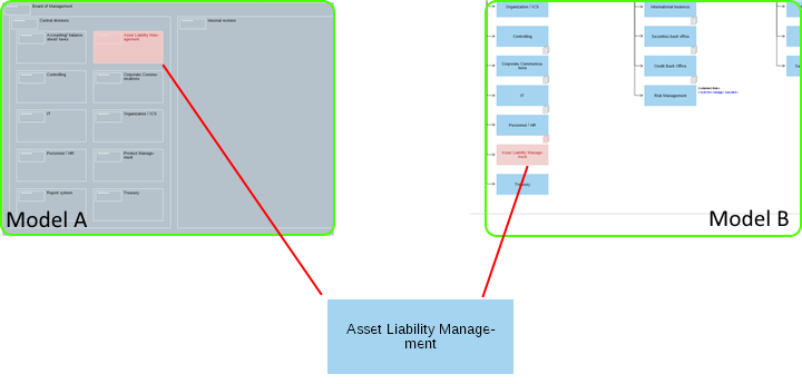
Drag Model/Object from Explorer to Graphical Editor
Drag the model or object you want to reference from the Explorer to the desired object on the drawing area. A blue border will appear around the target object. When you release the mouse button, ADONIS NP will show you which relations are possible and let you decide which one to create.
Nest Objects within Graphical Editor
Within the graphical editor, drag one object onto another. The objects may overlap, or be completely contained. A blue border will appear around the target object. When you release the mouse button, ADONIS NP will show you which relations can be created in this way. Simply choose the desired relation and it will be created.
This method can be used with existing objects, when you create new objects and when you copy and paste objects in the graphical editor.
Depending on the Application Library, different relations may be created by nesting objects. In the ADONIS BPMS Application Library, this functionality is available when you:
attach an Intermediate Event (boundary) to a Task or Subprocess
attach a Cross-reference to an object
attach a Note to an object

Convert Element Type
You can convert the element type (Task type, Event type etc.) in the graphical editor. Use cases such as the following are supported:
convert a Start Event with an unspecified trigger into a Signal Start Event
convert the Loop type of a Task from Not specified to Standard
convert a Message Intermediate Catch Event into a Timer Intermediate Catch Event
This functionality is available in Business Process Diagrams, Conversation Diagrams and Choreography Diagrams.
To convert the element type, proceed as follows:
Select the object you want to transform. When you do that, the modelling assistant appears.
Click the Conversions icon
 .
.Select the type you want to convert the element to.
If the modelling assistant does not appear, it may be disabled. For details on how to adapt your personal settings, please refer to the section Modelling.
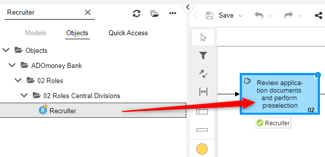
Reuse Objects
In order to re-use a single (repository) object from the Object Catalogue in the active model, proceed as follows:
- Drag the object you want to re-use from the Object Catalogue to an empty space on the drawing area (multiple selection is possible).
If you re-use an object which contains relations to other objects in the active model, the corresponding connectors will be automatically drawn.
Differentiation between Repository Objects and Modelling Objects
ADONIS NP distinguishes between repository objects and modelling objects. Repository objects are created and maintained in the Object Catalogue or in models. They can be reused in different models. Modelling objects, by contrast, are maintained only in the models in which they are created. They are not contained in the Object Catalogue.
Repository objects can be reused. Modelling objects cannot be reused.
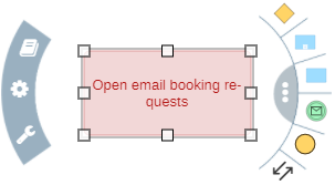
Move Objects in the Graphical Editor
You can move objects individually or collectively in the graphical editor:
Move Object
- Move a single object by drag and drop.
Move Multiple Objects
Hold the left mouse button and drag a (red) frame around the objects.
Move the objects to their new position by drag and drop.
Move Object to the Front or Back
- Right-click the object, and then click Move to front or Move to back.
Select Container Object
Due to practical reasons, you cannot select container objects (e.g. a Pool or Lane) with a single click. You have two options:
Click and hold the container object until it turns red or:
Click the header of the container object.